Optipedia • SPIE Press books opened for your reference.
An explanation of fibers from Field Guide to Illumination
Excerpt from Field Guide to Illumination
Fibers—Basic Description
Optical fibers, lightpipes, and lightguides are all variations on the same theme. They each contain a central transparent core, usually circular in cross-section, surrounded by an annular cladding. The cladding has a lower index of refraction than the core.

The core can transmit light for long distances with low loss because of total internal reflection at the interface between the core and the cladding. The primary purpose of the cladding is to maintain the integrity of this interface. Without it, total internal reflection would occur at a core-air interface, but dust, nicks, abrasions, oils, and other contamination on the interface would reduce the transmission to unacceptably low levels.
| Sometimes layers of buffering and/or jacketing are placed outside the cladding for additional protection. |
The core diameter can range from very small, on the order of the wavelength of light, to a centimeter or more. The very thin cores are essentially waveguides and not used for illumination. Flexible glass and quartz fibers have core diameters ranging from approximately 50 microns to about 1 millimeter. If they are thicker than that, they are rigid and called rods or light pipes. Plastic fibers are flexible at thicker core diameters. Sometimes liquid cores and plastic cladding are used to make flexible, high-transmittance lightguides that are over a centimeter in core diameter.
Numerical Aperature and Étendue
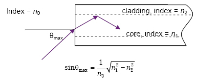
The maximum angle that a fiber can accept and transmit depends on the indices of refraction of the core and cladding (as well as the index of the surrounding medium, usually air, n0 = 1).

and the NA is

The fiber has a maximum acceptance projected solid angle, Ω = πsin2θmax, and an acceptance area, the crosssectional area of the core. Together, they define a throughput or étendue for the fiber in air:

where d is the core diameter.
This étendue defines the maximum flux-carrying capability of the fiber when presented with a source of radiance.
| Note: A fiber illuminated at less than its maximum acceptance angle will, theoretically, preserve the maximum illumination angle at its output. However, bending and scattering at the core-cladding interface broadens this angle toward the maximum allowable. This effect is not important in illumination systems in which it is desirable to utilize the maximum étendue of low-throughput components such as fibers and fill the full input NA. |
Fiber Bundles
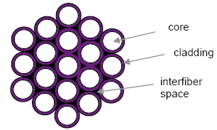
To achieve high throughput with flexible glass or quartz fibers, multiple fibers are often arranged in a bundle, such as the 19-fiber tightly packed bundle shown below:

The ratio of the light-carrying core area to the area of the entire bundle is called the packing fraction (pf), and can be as high as 85%. This packing fraction reduces the effective area of the bundle and, correspondingly, its étendue.
In addition to flexibility, fiber bundles have other possible advantages in illumination systems:
Shape Conversion: In some situations, such as when illuminating a spectrometer, it can be useful to convert a circular cross-section of fibers to a line cross-section to align with, or actually become, the entrance slit to the spectrometer.
Splitting the Bundle: By feeding a large fiber bundle with a single light source and splitting the bundle into two or more branches, it is possible to illuminate multiple locations, from multiple angles, with one source.
Mixed Bundle: When illuminating with light over a wide spectral band, such as the full solar spectrum (~250 to 2500 nm), a mixed bundle of high OH silica fibers for good UV transmission and low OH silica fibers for good IR transmission can compensate for the lack of an adequate single-fiber type.
Tapered Fibers and Bundles
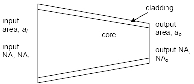
By tapering a single fiber, it is possible to trade off between area and solid angle while keeping the product (étendue) approximately constant.

ai·NAi2 ≈ ao·NAo2 |
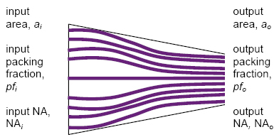
On the other hand, when a bundle of straight fibers is tapered, the tradeoff is between the area and packing fraction.

NAo = NAi = NAfiber |
ao·pfo = ai·pfi |
A. V. Arecchi, T. Messadi, and R. J. Koshel, Field Guide to Illumination, SPIE Press, Bellingham, WA (2007).
View SPIE terms of use.

