Optipedia • SPIE Press books opened for your reference.
Explanation of moiré - Field Guide to Interferometric Optical Testing
Excerpt from Field Guide to Interferometric Optical Testing
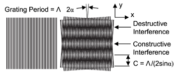
In optics, moiré refers to a beat pattern produced between two gratings of approximately equal spacing. Examples of moiré can be seen using household items, such as overlapping two window screens or with a striped shirt seen on television. In 1874, Lord Rayleigh pioneered the use of moiré for reduced sensitivity testing. Moiré is useful to help understand basic interferometry.

The basic idea in using moiré for optical testing is to project a fringe pattern or grating onto an object and then view it from a different angle. Surface topography can be recovered from the resulting moiré pattern. This technique is capable of contouring surfaces that are too coarse or have too much deviation for traditional interferometry. Mathematically, the moiré pattern is the product of the two gratings. In general, the fringe spacing C in the moiré pattern from two straight-line gratings of period Λ1 and Λ2, oriented 2α from each other is given by:

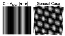
 In the above figure, Λ1 = Λ2 = Λ. On the left, α = 0 but Λ1 ≠ Λ2, so the fringe spacing equals the beat wavelength.

On the right, the gratings are tilted and Λ1 ≠ Λ2. If Λ1 is known and C is measured, then Λ2 and α can be found.
Moiré and Interferograms
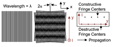
The single grating in the figure below can be thought of as a snapshot of a plane wave traveling in the +x direction with the grating period Λ replaced with the wavelength of light, λ. The moiré pattern on the right can be thought of as two plane waves from an interferometer traveling in the +x direction with an angle of 2α, frozen in time. Since λ1 = λ2, the regions of destructive and constructive interference remain stationary in y. The moiré from two straight line gratings correctly predicts the centers of the interferencefringes produced by interfering two plane waves (tilt fringes) but not the sinusoidal fringe pattern.

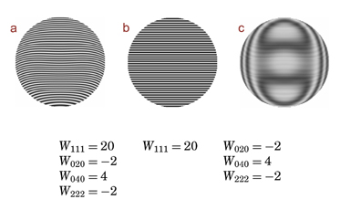
The moiré pattern resulting from superimposing (multiplying) two interferograms (a and b) shows the difference inthe aberrations between the two (c).

E. P. Goodwin and J. C. Wyant, Field Guide to Interferometric Optical Testing, SPIE Press, Bellingham, WA (2006).
View SPIE terms of use.

